|
|
Chestnut Hill Pumping Station
Zum Vergrößern Bild anklicken
| Name | Chestnut Hill Pumping Station |
| Ortssitz | Boston (Mass.) |
| Straße | Beacon Street 2436 |
| Postleitzahl | MA 02167 |
| Art des Unternehmens | Wasserwerk |
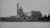
| Anmerkungen | Wasserwerk der Metropolitan District Commission, 1887 zur Versorgung höhergelegener Stadtteile gebaut. Architekt: Artur H. Vinal (1854-1923) und Edmund March Wheelright. Beginn der Wasserversorgung in Boston: 1848 durch Schwerkraft, seit 1878 auch aus dem Sudbury River. Liegt gegenüber dem Chestnut Hill Reservoir, dem Knotenpunkt für die Wasserversorgung Bostons. Pumpte Wasser ins Fisher Hill Reservoir (125 ft. höher), von dort mit Schwerkraft in die Stadt. Insgesamt waren fünf Maschinen installiert; drei sind noch vorhanden. Die Gebäude wurden bis 2002 für überflüssig erklärt, litten eine Zeitlang unter mangelnder Unterhaltung und wurden 1998 auf die Liste der zehn am meisten gefährdeten Stätten des Staates gesetzt. Umgewandelt in "Metropolitan Waterworks Museum" (s.d.) |
| Quellenangaben | [ASME: The Leavitt Pumping Engine ... (1973) Internet] [Tribe: Compound Corliss engines (1903) 140] [Laskey: History of Boston's water system (2014), ab Zeit 1887] [Brackett: Metropolitan Water Works (1905) 34] |
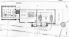
| Hinweise | [Laskey: History of Boston's water system (2014)]: Grundriß (1887); [Brackett: Metropolitan Water Works (1905) 36]: Low Service Pumping Station; [38]: High Service Pumping Station |
| Zeit |
Ereignis |
| 1846 |
Ellis Sylvester Chesbrough wird Chefingenieur der Wasserwerke |
| 1855 |
Ende der Amtszeit von Ellis Sylvester Chesbrough als Chefingenieur der Wasserwerke |
| 1887 |
Bau des Pumpwerks an der Südseite des Chestnut Hill Wasserbehälters in Brighton. Die Gebäude entstehen aus Milford-Granit und Longmeadow-Sandstein |
| 1888 |
Inbetriebnahme des Pumpwerks |
| 1894 |
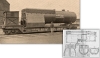
Aufstellung der von E. D. Leavitt entworfenen Riedler-Dampfpumpe (Pumpe Nr. 3) im Chestnut Hill Wasserwerk, Boston |
| 1895 |
Gründung des "Metropolitan Water District", und das Versorgungsgebiet wird in ein nördliches und ein südliches aufgeteilt. Das südliche recht bis Quincy und Hyde Park und wird von Chestnut Hill versorgt. |
| 1897/98 |
Gemäß den Bostoner Architekten Wheelwright & Haven wird die Pumpstation erweitert. Eine neue Dreifachexpansionspumpmachine (No. 4), bestellt 1898, gebaut von E. P. Allis Company, wird aufgestellt. |
| 1901 |
Bau der Low-Service Pumping Station (Station Nr. 2 mit drei Holly-Gaskill Triplex-Maschinen) |
| 1911 |
In der Low-Service Pumping Station wird eine vierte Holly-Gaskill Triplex-Maschine aufgestellt |
| 1921 |
Entfernung der Holly-Gaskill Pumpmaschine Nr. 2 |
| 1922 |
Eine Worthington-Snow Pumpmaschine (Nr. 4) wird in der High-Service Station an Stelle der Holly-Gaskills-Maschine aufgestellt. Sie hat fast die doppelte Fördermenge wie ihre Vorgängerin. |
| 1928 |
Die Leavitt-Riedler Pumpmaschine (Nr. 3) geht außer Betrieb |
| 1931/32 |
Entfernung der Holly-Gaskill Pumpmaschine Nr. 1 |
| 1954 |
Umstellung von Kohle- auf Ölfeuerung |
| 1954 |
Aufstellung von Pumpen mit Dampfturbinenantrieb |
| 1954 |
Die Allis-Pumpmaschine (Nr. 4) geht außer Betrieb |
| 1976 |
Das Werk geht außer Betrieb Damit endet die Betriebszeit der Worthington-Snow Pumpmaschine |
| 27.03.2011 |
Eröffnung des Wasserwerksmuseums |
| Produkt |
ab |
Bem. |
bis |
Bem. |
Kommentar |
| Trinkwasser |
1888 |
Beginn (erbaut) |
|
|
|
| Zeit |
Objekt |
Anz. |
Betriebsteil |
Hersteller |
Kennwert |
Wert |
[...] |
Beschreibung |
Verwendung |
| 1905 |
Dampfkessel |
3 |
Low-duty |
Atlantic Works |
|
|
|
D= 97 7/8", mit 384 Rauchröhren D= 2", L= 15'. Mit Green-Ecomomizer mit 144 Röhren |
|
| 1905 |
Dampfkessel |
2 |
High -duty |
unbekannt |
Heizfläche je |
|
qm |
Senkrechte Röhrenkessel. D= 98", L= 24,33', 392 Röhren |
|
| 1905 |
Dampfkessel |
2 |
High-duty |
unbekannt |
Heizfläche je |
|
qm |
liegende Röhrenkessel. D= 64", L= 18.42', 102 Röhren |
|
| 1905 |
Schornstein |
1 |
Low-duty |
unbekannt |
Höhe |
|
m |
H= 125 ft., äußere Durchmesser: 13 ft. unten und 8 ft. oben; Innendurchmesser: 6' 6" |
|
| ab 1895 |
Dampfkessel |
1 |
f. Leavitt-Maschine |
Atlantic Works |
Heizfläche |
|
qm |
Großer Feuerbüchskessel mit doppelter Feuerbüchse und doppelter Verbrennungskammer (wasser-durchspülte Trennwand mit Stehbolzen), Belpaire-Stehkessel; D= 90", L= 34,33', 201 Röhren, D= 76 mm |
Dampfversrgung für Leavitt-Maschine |
Zeit = 1: Zeitpunkt unbekannt
| ZEIT | um 1905 |
| THEMA | Chestnut Hill Reservoir |
| TEXT | The Chestnut Hill Reservoir is located in the Brighton district of the city of Boston, about five miles from the State House. It receives water from the Sudbury and Cochituate aqueducts, and serves as a storage reservoir from which the pumps at the high and low-service stations draw their supplies. This reservoir was built by the City of Boston, and completed in the year 1870. Its high water mark is 134 feet above Boston city base, and previous to the year 1900 the greater portion of the city of Boston was supplied from this reservoir by gravity. The reservoir consists of two basins having areas of 87 1/2 and 37 1/2 acres respectively. It was constructed by building a dam 2,000 feet long, with a maximum height of 35 feet, across a valley, removing the soil from the enclosed basin and paving the slopes. The dam is built of earth put on in layers, watered and rolled, and near the center of the dam is a core of clay puddle 10 feet thick at the base and 4 feet at the top. The slopes of both basins of the reservoir are covered with stone paving 2 1/2 feet in thickness, which extends 8 1/2 feet from the top of the bank measured vertically. Connected with the reservoir there are five gate-chambers through two of which water is admitted to the reservoir from the Sudbury and Cochituate aqueducts; one contains gates which control the flow between the two basins and also admits water from the Cochituate aqueduct, and through one water is drawn to the two pumping stations. The large gate-chamber at the east end of the reservoir was used as an effluent gate-chamber previous to the year 1900, while water was supplied from the reservoir by gravity, but at present all the gates are closed. |
| QUELLE | [Brackett: Metropolitan Water Works (1905) 34] |
| |
| ZEIT | um 1905 |
| THEMA | Pumping Stations |
| TEXT | All water delivered into the Chestnut Hill Reservoir by the Sudbury and Cochituate aqueducts is pumped at two stations
located on the southeasterly side of the reservoir. At one station water is pumped to supply the higher land in the
southern portion of the Metropolitan District; at the other it is pumped into mains leading to Spot Pond, which is the
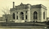
principal distributing reservoir for the lower portion of the District. On the shore of Spot Pond, in Stoneham, there is a pumping station from which water is pumped to a reservoir supplying the higher levels in the northern part of the District. At two smaller stations, one in the West Roxbury district of Boston and one in the town of Arlington, water is pumped to supply small districts situated above the elevation supplied from the larger stations at Chestnut Hill and Spot Pond. The low-service pumping sation at the Chestnut Hill Reservoir has exterior walls of buff Bedford Indiana limestone. The building contains an engine room 134 feet by 60 feet, 41 1/2 feet in height from the floor to the under-side of the roof trusses, a boiler room 62 feet by 40 feet, a coal house 89 1/2 feet by 48 feet, a dynamo room 38 feet by 17 feet, and a tower 19 feet square in which is located a steel equalizer and overflow tank 13 1/2 feet in diameter and 33 feet high, having a capacity of 31,000 gallons. The interior facing of the engine room walls is of buff brick with red brick trimmings, and the floor is of green slate tile. The chimney is 125 feet high, 13 feet in exterior diameter at the base and 8 feet at the top under the cap. The flue is 4 feet 6 inches in diameter. The machinery consists of three 35.000.000-gallon vertical triple expansion crank and fly-wheel engines, designed and built by the Holly Manufacturing Company of Lockport, N.Y., and three vertical fire tube boilers designed by Dean and Main and built by the Atlantic Works of East Boston. The engines have steam cylinders 17, 31 1/4 and 48 inches in diameter, pump plungers 37 inches in diameter, and both pistons and plungers have a stroke of 60 inches. These engines draw their supply from the Chestnut Hill Reservoir, and raise it from 45 to 60 feet. On the contract trial they gave a duty of 156.322.000-foot pounds per 100 pounds of dry coal. The boilers are 97 7/8 inches inside diameter, 29 1/2 feet high over all, and contain 384 2-inch tubes 15 feet long. A Green economizer, with 144 tubes, is located in the smoke flue between the boilers and the chimney. The coal house has a capacity of 1,000 tons, and is so arranged that loaded cars are run into the building about 15 feet above the floor. The high-service pumping station has exterior walls of pink
Milford granite with brownstone trimmings. The engine room contains two 8.000.000-gallon Gaskill engines built by the
Holly Manufacturing Company, of Lockport, N. Y., one 20.000.000-gallon triple expansion engine designed by E. D. Leavitt and built by the Quintard Iron Works, of New York, N.Y., and one 30.000.000-gallon vertical, triple expansion,
crank and fly-wheel engine, designed and built by the E. P. Allis Company of Milwaukee, Wisconsin. The boiler room
contains one boiler of the Belpaire type, two internally fired verticle fire-tube boilers, and two externally fired fire-tube boilers. These engines pump water from the Chestnut Hill Reservoir for the supply of the southern high-service district, raising it from 120 to 130 feet into the Waban and Fisher Hill reservoirs. |
| QUELLE | [Brackett: Metropolitan Water Works (1905) 34] |
|