|
|
Robert H. Ramsey
Zum Vergrößern Bild anklicken
| Name | Robert H. Ramsey |
| Ortssitz | Philadelphia (Penns.) |
| Straße | East Chelten Avenue 239 |
| Art des Unternehmens | Erfinder |
| Anmerkungen | Erfinder einer Umsetzvorrichtung für Eisenbahnwagen ("Ramsey's Truck Shifting Apparatus and Car Transfer Apparatus") bei Spurweiten-Wechsel durch Tausch der Drehgestelle. Obige Adresse lt. Publikation von 1883 (National Exposition of Railroad Appliances, Chicago). 1886: 110 South Fourth Street. 1891: Büro im Drexel Building 743. War 1884 noch britischer Staatsbürger. Vmtl. nicht Teilhaber bei der "Pullman, Kimball and Ramsey Sleeping Car Co." (gegr. am 19.05.1866), da Ramsey zur Zeit der Gründung erst 22 Jahre alt war. |
| Quellenangaben | [Philadelphia and popular Philadelphians (1891) 134] [Ramsey: Ramsey's car transfer apparatus (1883)] [Klein/Hoogenboom: History of Pennsylvania (1973) 302: Anzeige] |
| Zeit |
Ereignis |
| 1844 |
Geburt von Robert H. Ramsey in Cobourg, Ontario |
| 21.05.1878 |
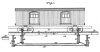
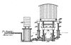
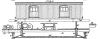
Erteilung des U.S.Patents Nr. 204.087: Car-Transfer Apparatus (zum Umspuren von Eisenbahnwagen). Seitliche Fahrgestelle stützen den Wagenkasten in unveränderter Höhe, während die Fahrgleise (beider Spurweiten) in eine Grube abtauchen, so daß die die Drehgestelle abgesenkt und vom Wagenkasten frei werden. Sie können dann weggerollt und gegen solche der anderen Spurweite getauscht werden. Beim gemeinsamen Zurückziehen setzen die Wagenkästen auf den gewechselten Drehgestellen auf. |
| 02.09.1884 |
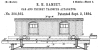
Erteilung des U.S.-Patents Nr. 304.562 "Car and freight transfer apparatus" |
| 20.08.1922 |
Tod von Robert H. Ramsey in Germantown, Pennsylvania |
| Tätig |
ab |
Bem. |
bis |
Bem. |
Kommentar |
| Umspurvorrichtungen |
1878 |
1. Patent |
1891 |
[Philadelphia] |
mit Stützwagen bzw. mit Hydraulikhebern |
| Umspurvorrichtungen |
1878 |
1. Patent |
1891 |
[Philadelphia] |
unsicher, durch wen gebaut |
Zeit = 1: Zeitpunkt unbekannt
| ZEIT | 1884 |
| THEMA | Patentschrift Spurwechsel-Vorrichtung |
| TEXT | Application filed February 13, 1884. (No model.)
To all whom it may concern.
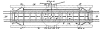
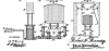
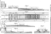
Be it known that I, ROBERT H. RAMSEY, a subject of the Queen of Great Britain, residing in the city and county of Philadelphia, State of Pennsylvania, have invented a new and useful Improvement in Apparatusfor Transferring Cars, Freight, &c., which improvement is fully set forth in the following specification and accompanying drawings, in which Figures 1, 3, and 4 are side elevations of apparatus for transferring cars, freight, &c., embodying my invention, the cars being shown indifferent positions. Fig. 2 is an end view of Fig. 1. Fig. 5 is a top or plan view. Fig. 6 is an end view of the apparatus when the car is in the position I shown in Fig. 4. Fig. 7 is an end View of a modification on a reduced scale. Similar letters of reference indicate corresponding parts in the several figures.
My invention consists of a method of and means for transferring cars to rails of either broad or narrow gauge railroads, or furnishing car-bodies with different trucks-for such railroads, by the employment of rails of different levels or steps with vertically-movable supports for the car-body, and trucks between said steps, so that the cars may descend from one step to the other and store or furnish power to restore the supports to their normal position.
Referring to the drawings, A represents a vertically-moving table, on which are laid rails a and b for broad and narrow gauge railroads, said table being mounted on pistons B of hydraulic cylinders G, which latter are sustained in a pit between rails D D, which, arranged at different levels, are adapted for broad and narrow gage railroads, and properly laid on a road-bed, it being seen that when the table is in its highest position its rails are continuous of the rails D, and when in the lowest position its rails are continuous of the rails D. E represents vertically moving beams which are arranged parallel with the sides of the table A, and mounted on the pistons F of hydraulic cylinders G, which are sustained in the pit in which the cylinders C are contained.
Connected with the cylinders C and G are pipes H H, which are in communication with an accumulator, J, which is sustained in the afore mentioned pit, or adjacent thereto. The stem of the piston of said accumulator projects through the upper head thereof, and has placed on weight, K. On the table A, at the center thereof is mounted a turntable, L, which is provided with rails c and d, of broad and narrow gauge, which may be placed in communication with the rails a and b, or rails a' b', mounted on the roadbed at a right-angle to said rails a and b.
The operation is as follows: When a carbody is to be transferred to trucks of different gauge, the car is run on the table A from the rails or step D, as seen in Fig. 1. Cross-bars M are then placed transversely under the carbody and rested on the beams E. The valves of the cylinders G are now opened, whereby the weight of the trucks on the table A causes the latter to descend, forcing the water from said cylinders in the accumulator and raising the weight K, it being noticed that as the valves of the cylinders G are closed the car-body remains supported by the bars M on the beams E. The table A reaches the lower rails or step, D', and the trucks are removed to the turn-table, whereby they may be run off to the siding. The valves of the cylinders C are meanwhile closed to prevent the water from returning to said cylinders, and the weight consequently from raising the empty table.
Trucks of the different gauge are then run on the table A, with their center plates placed directly under the king-bolts of the car-body. (See Fig. 3.) The valves of the cylinders G are now opened and the weight of the car-body depresses the beams E, forcing the water from said cylinders into the accumulator and raising the weight K to a greater extent the car-body now resting on the trucks, as shown in Figs. 4 and 6. The valves of the cylinders G are now closed to prevent the water from reentering the said cylinders, and the bars M are withdrawn, so that the car may be run from the table A to the rails or step D, which connects with suitable sidings leading to the main track, it being evident that the upper rails or step, D', also connects with suitable sidings leading to the main track. The table A and beams E are now empty and depressed to the lowest point. This is an important feature, for the descent of the trucks and car-body has raised the weight K on the piston of the accumulator, and thus created a power which is availed of for subsequent service. The valves of all of the cylinders are now opened and the weight K is uncontrolled, and so descends, forcing the water from the accumulator into the several cylinders, thereby raising the table and beams until the table is again on alevel with the upper rails or step D, so that another car may be placed on the table, the other operations being repeated, it being seen that each car that is transferred furnishesh power to return the table and beam to their normal position, ready for the next car. The cylinders G may be advantageously placed in a frame above the car, as shown in Fig. 7 and their piston-rods project downwardly therefrom and have connected with them the beams E. Depending from the beams are hooks M, which may be placed under the carbody to sustain the sa1ne,similar to the bars M. When the bars M are used, they may be held somewhat tightly on the beams E, when the car-body is lowered on the substitute trucks. To prevent this set-screws or eccentrics may be arranged on the beams and have the bars rest thereon, whereby by operating the screws or eccentrics the bars may be relieved. Another method of relieving the bars is by the employment of an auxiliary cylinder located aside of the accumulator, when by opening the valves of the pipes leading from the cylinders G to said auxiliary cylinder the weight of the beams E will force water into said auxiliary cylinder and raise the plungers thereof sufficiently to relieve the bars, said plungers being afterward depressed by the action of the weight K. While I have described thecylinders ashydraulic, I do not limit myself to the use of water therein, as glycerine, oil, air, or other fluid may be employed in lieu thereof.
In lieu of cross-bars M, I may use arms which are pivoted, hinged, or otherwise attached to the beams E, or frames aside thereof, so as to be i moved in and out of position and remain connected with the beams or frames, as desired.
Having thus described my invention, what I claim as new, and desire to secure by Letters Patent, is:
1. A step in a track, vertically-movable supports for cars between the same, and devices whereby said supports may be automatically operated, and the transfer of trucks of broad and narrow gages may be accomplished by gravity, substantially as and for the purpose set forth.
2. A transfer apparatus consisting of steps, vertically-movable supports for cars between the same, and a weight connected with said supports, substantially described, whereby ears may descend from one step to the other and furnish power to restore the supports to their normal position.
3. A step in a track, vertically-movable supports for cars between the same, fluid-cylinders with pistons on which said supports are rested, an accumulator, and a weight superimposed on the piston of the accumulator, substantially as and for the purpose set forth.
ROBERT H. RAMSEY
Witnesses: John A. Wiedersheim, A. P. Grant. |
| QUELLE | https://patents.google.com/patent/US304562 |
| |
| ZEIT | 1891 |
| THEMA | Beschreibung |
| TEXT | Foremost among the inventors of the present generation may well be named Mr. R. H. Ramsey, whose car transfer apparatus, now in use on 40 lines of railroad in the United States, is one of the most wonderful as well as useful inventions of the age. Mr. Ramsey was born in Cobourg, Out., in 1844, and was educated in the public schools of his native town. At the age of seventeen he became engaged in the freight business, and from his observations while thus engaged he wrought out this wonderful apparatus by means of which, without skilled labor, and by force of gravity alone, car bodies are raised and replaced upon the trucks with greatest possible dispatch and without straining of joints, and without cracking the varnish on passenger and sleeping coaches, both of which are incident to the use of jacks. Mr. Ramsey first took out his patent in 1876, and two others in May, 1878, and the year last named he introduced his system to general notice. The price and terms of a patent license granting the right to construct and operate the apparatus, are placed at a figure that enables any company to use it with profit, and will be made known on application to Mr. Ramsey at his office No. 743 Drexel Building, Philadelphia. His system is now in use on the Union Pacific, W. N. Y. & P., Pittsburg & Western, Savannah, Florida & Western, Utah & Pacific, and many other railroads, and he received numerous medals from Franklin Institute, World's Industrial Exposition, New Orleans, 1885, National Exposition of Railway Appliances, Chicago, 1883, and other expositions. His invention is also extensively used in Russia, Australia,
Brazil, Norway, India and elsewhere on the Eastern Continent. He has also copyrighted an engineer's device or chart for locating any section or part of section in any township and range where that system obtains, which is of great utility. |
| QUELLE | [Philadelphia and popular Philadelphians (1891) 134] |
|