|
|
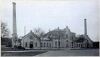
North Point Pumping Station
Zum Vergrößern Bild anklicken
| Name | North Point Pumping Station |
| Ortssitz | Milwaukee (WI) |
| Art des Unternehmens | Wasserpumpwerk |
| Quellenangaben | [Carpenter: Report of test of pumping engine at Milwaukee, North Point Pumping Station (1893)] |
| Hinweise | [Carpenter: Report of test of pumping engine at Milwaukee, North Point Pumping Station (1893)]: Ansicht |
| Produkt |
ab |
Bem. |
bis |
Bem. |
Kommentar |
| Handel |
1822 |
Beginn an der Rheinschanze |
|
|
|
| Trinkwasserförderung |
1892 |
Allis-Pumpmaschine |
1892 |
Allis-Pumpmaschine |
|
| Bezeichnung |
Bauzeit |
Hersteller |
| Dampfpumpmaschine |
1893 |
Edw. P. Allis & Co., Reliance Works |
| ZEIT | 1893 |
| THEMA | Versuche an der Allis-Dreizylinder-Pumpmaschine |
| TEXT | The engine tested is a triple expansion, vertical engine with the three cylinders arranged side by side. The engine was built by the Edward P. Allis Co., and designed by Irving H. Reynolds under general supervision of Edwin Reynolds, general superintendent of the Allis works. The general appearance of the engine is well shown in Figure 1, as it appears from the engine-room floor. The pumps are entirely below the floor and the piston rods from the engine are directly connected to the plungers of the pumps. It has two fly-wheels, which are connected to the main shaft, and perform the office simply of aiding in the regulation of the engine. The engines and pumps have in each case five feet stroke, the diameters of the engine cylinders being respectively 28,48 and 74 inches and are double acting. The diameter of the pump plungers are 32 inches and in each case are single acting. Between each two cylinders of the engine is a large receiver, which is reheated by pipes containing high pressure steam. The volumes of these receivers are respectively, high pressure 101.3 cu. ft., intermediate receiver 151 cu. ft. The engines are in each case steam jacketed, in the high pressure and intermediate cylinders these jackets are supplied with live steam at boiler pressure; but on the low pressure cylinder the jacket is supplied with steam which passes through a reducing valve and which has a constant pressure of 34 pounds. In each case the cylinders are jacketed on both heads and barrel. The steam is supplied to the high pressure jacket by a pipe leading directly from the main steam pipe, the exhaust from this jacket supplies the jacket of the intermediate cylinder and this is led into a trap, the overflow of which ordinarily passes into the suction of the feed pump for supplying the boilers. The exhaust steam from the low pressure cylinder jacket is similarly received into a steam trap and also discharged into a feed pipe. The valves of the engine are arranged as follows : The admission valves of all the cylinders are of the Corliss type and operated in the usual manner, so are also the exhaust valves of the high and intermediate cylinders. The exhaust valves of the low pressure cylinder are, however, poppet valves and when closed are flush on the inside of the cylinder head, thus eliminating any clearance due to exhaust ports. All the valve ports are located in the cylinder heads. The governor is of the ordinary fly-ball type with special arrangements for controlling this style of engine. It is connected only to the high pressure cut-off mechanism, and controls the engine only at maximum speed. The other cut-offs are operated by hand mechanism, as is also the high pressure at low speed. In each engine are two piston rods, which are connected to a cross-head, and this in turn is connected to the pump plungers by four tie rods. The clearances in the different engine cylinders, as given by the makers, are respectively, high pressure, 1,4 percent.; intermediate cylinder, per cent.; low pressure cylinder, 0.777 of one per cent. The arrangement of the pumps is shown very clearly by Fig. 2, which gives a plan of engine foundation, position of pumps, position of boilers and arrangement used for supplying feed water. The pumps are located directly beneath the engine cylinders, and are designated by P on the drawing. The valves are located in a cylinder, the position of which is designated by VC on the drawing. The valves for these pumps, instead of being arranged on a single plain surface, are situated on the sides and tops of small hexagonal prisms. The valves themselves are rubber and about four inches in diameter, but their combined area is practically equal to that of the pump plunger. The water is received into the pump through the lower portion of the valve chamber, passing and lifting the suction valves, it then is, by the reverse motion of the plunger, forced outward and upward past the delivery valves in the upper part of the valve chamber. (Fig. 4.) The water is received into a well which is connected with Lake Michigan by a large masonry tunnel. The bottom of this well is 39.8 feet from the center of the pressure gauge on the main engine-room floor. The center of the valve chamber is 19.8 feet below the same gauge, and during the test the suction lift, from the center of valve chamber to the surface of the water, averaged 10.77 feet. The general arrangement of suction pipe is shown in the drawing, Fig. 2. The air pump, circulating pump, boiler feed pump, and the pump for supplying the air chambers with compressed air, were all directly connected to the moving parts of the engine and in each case had the same stroke. The circulating pump supplied the condenser with water, taking it from the suction side of the pump and returning it to the same side after having passed through the condenser. The condenser used was a surface condenser of the Wheeler pattern and was supplied with circulating water, as explained, the object of which was to remove nearly all the pressure from the condenser tubes. The dimensions of all the pumps are given with the data of the test. The boiler plant, from which the steam is derived for operating the engine, is situated in the adjacent room, as shown in the plan, Fig. 2. The boilers are in each case plain tubular boilers, with fixed grates, constructed by the builders of the engine, The Edw. P. Allis Co. The boilers are five in number, of which four were used during the test. The dimensions of each boiler are given in the annexed tables of the results. The discharge gases from the boiler were carried by a horizontal breeching over the front portion of the boiler to a large brick stack, 125 feet in height.
PREPARATIONS FOR TESTING.
The arrangement of the plant for the test is shown quite clearly in the plan view, Fig. 2. Arrangements were made for measuring the feed water supplied to the boilers and the amount of coal consumed during the time of the test. Indicator diagrams were taken once in fifteen minutes. Temperatures of feed water, discharge jacket water, the external air, engine-room and flue gases were taken and are given in the results. The total consumption of water used during the test is obtained by measurement of the feed water supplied to the boilers. This feed water was obtained from the hot well of another engine, and the condensed steam from this engine was, during the test, discharged into the overflow and wasted. The steam which was used to supply the jacket of the engine was measured by receiving the overflow from the various jacket-traps into weighing tank, No. 3, and returned as a portion of the feed water to the boilers. The method of measuring the feed water was to receive it into two barrels, each of which were carefully calibrated by weighing on a pair of scales when filled to a certain fixed overflow. The method of arranging the barrels for this purpose is shown in Fig. 2, from which it is seen that the overflow was a tube extending upward from the bottom to a certain height, the discharge of which was carried off in the waste and did not enter the feed water. The top of this overflow pipe was filled to a sharp edge and was made truly horizontal. From some experiments made with this type of weighing apparatus, the writer has been led to the conclusion that the error in each tank of water need not exceed one-twentieth of one pound, and is ordinarily much less than van be obtained by barrels standing on a pair of scales. During the test the feed water was supplied alternately to two barrels, arranged as explained, and numbered respectively 1 and 2, one barrel being filled while the other was emptying. The emptying was done through a valve, connected to a pipe, leading from the bottom of the barrel and arranged so that any drip could be plainly seen by an observer. The discharge from these feed tanks was led into a tank composed of two barrels connected together and standing on a lower level, to which the feed pump for the boilers was directly connected. The discharge water from the jackets was received in a barrel similarly arranged and discharging into the same barrels as Nos. 1 and 2. During the test one attendant was supplied to operate the valves on each of the weighing barrels, and, in addition, two observers, one of whom was supplied by the builders of the engine, the other by the party from Cornell University, kept independent logs of the water supplied to the boilers. In each case the time of emptying the measuring tanks was recorded, also the number of the barrel emptied at the time. The measuring barrel for the jacket water, which is designated No. 3 on our log, was supplied with a float for measuring the amount of water instead of the overflow, as described for the other measuring tanks. This barrel was emptied in each case whenever the float reached a certain standard height, the corresponding weight of water for that case being obtained by weighing. With this barrel the percentage of error would be, as compared with the others, relatively large, but as the total number of times that barrel No. 3 was emptied was comparatively small, the effect on the result was correspondingly reduced. The actual error in barrel No. 3 may have reached one-half of one per cent., but as the amount measured in this barrel was less than 8 per cent, of the whole amount used, this error becomes insignificant. The log gives the total amount of feed water without correc¬ tion of any sort, but, in obtaining the full amount of water used in the jackets of the engine, a correction was found necessary, which does not in any way affect the total result, but simply the division or percentage which was consumed in the jackets. This correction was necessary for the reason that the discharge of water from the jacket-traps was at a temperature due to the pressure of steam on the jackets. This being in excess of 212 degrees gave considerable loss, due to evaporation. Most of this evaporation was prevented by passing the pipe from the jacket-traps through a large body of cold water and closely covering the top of barrel No. 3, into which this water was received. Still, however, some loss from evaporation occurred, and a careful test was made to determine the amount of this evaporation by allowing the barrels to stand for a given time on a pair of scales when in the same condition as during the test. The results of this test indicated a loss due to evaporation of from 60 pounds as a minimum to 120 pounds as a maximum of steam per hour ; in making up the percentage that jacket water bears to the whole, the maximum correction was used. This is certainly sufficient to account for the full amount used in the jackets. Had no correction been made for this, the total amount of jacket steam as given by barrel No. 3 would have been about 8 per cent, of the whole, but using the correction, as explained, the jacket water becomes 9.25 per cent, of the total. The fuel burned during the test was carefully weighed as it was brought into the boiler-room, and the results were checked by two independent observers, one of whom was furnished by the engine builders, the other by our party. The arrangement for measuring the temperature of the flue consisted in inserting a thermometer, the accuracy of which had been tested and which could read to 700 degrees F., in the upper portion of the breeching and also by inserting a pyrometer into the center of the breeching directly beneath the thermometer. The thermometer used was one in which nitrogen gas of low density occupied the space directly above the mercury. The pyrometer was of a kind in which the pressure of a hydro-carbon vapor was used as a means of measuring the temperature. The one used being manufactured by Schäffer & Budenberg and called by them a thalpotasimeter. The readings of the two instruments, as shown by the log of the test, differed but few degrees. The thermometer in the top part of the flue generally reading 2 to 8 degrees higher than the pyrometer, and was much more sensitive to changes in temperature. The quality of the steam was measured by attaching a throttling calorimeter of the kind designed by the writer, and manufactured by Schäffer & Budenberg, to the main steam pipe directly above the boilers. The connection was made very carefully by screwing a long perforated nipple into a vertical portion of the main steam pipe. During the test the steam pressures varied only a few pounds, the water level in the boilers was kept very nearly constant, so that the determinations made with the calorimeters showed, in every instance, a uniform quality of steam, as might have been expected. This quality was 98.95 per cent, throughout the whole test. The boilers were carefully examined for leaks. Some leakage being detected in the blow-off pipes, these were disconnected and their ends plugged several hours before commencing the test. A slight leak of steam was found in one of the joints of the main steam pipe between the boilers and the engine. This leak could not be stopped; it was, however, of small amount and no correction was made for it. The reducing motions used on the engines were supplied by the makers, and were reducing wheels with threaded or spiral grooves for the cords, so that the diameters were kept constant. The reducing motion was accurate and the diagrams taken were satisactory in every respect. The draft-gauge was a simple U-shaped manometer, with vernier attachment for reducing small variations in pressure, the form used being that manufactured by the Hartford Boiler Co. This was attached to a small pipe nipple inserted into the side of the breeching at a point near the pyrometer. The flue gas was obtained from time to time during the test and analyzed immediately. The apparatus used being a portable form of Orsat’s apparatus, known as Fisher’s gas analysis apparatus. A full description, with method of using, is given on pages 432-6 in Text-book of Experimental Engineering, and need not be described here. A sample of the gas was obtained from a perforated nipple extending into the center of the breeching and was drawn by an aspirator directly into the apparatus for analysis.
CHARACTER OF THE COAL.
The coal burned during the test was from the Pocahontas mine, Virginia. It was a soft, black coal, very uniform in character, and, as shown by the analysis made later by Geer and Garrels at Sibley College, was very high in fixed carbon and possessed very little ash. The coal was slightly damp, and on drying a weighed sample for 48 hours over the boilers a reduction in weight of 5.2 per cent, occurred. By mixing several portions of the coal taken from various parts of the pile together, and selecting a small quantity, a sample was obtained for analysis at Sibley College. This coal was shipped by express in a bag, was several days on the journey and was apparently much drier than the coal used during the test. It, however, showed 3.62 per cent, of moisture after reaching Sibley College. During the test the amount of ash found under the grates and after thoroughly shaking the fire was less than 1 per cent. The analysis which was made at Sibley College showed 1.47 per cent, of ash. The discrepancy probably being due to ash drawn into the chimney by the draft, the total difference required for this would be a loss equal to less than 80 lbs. for the whole test. The analysis of the coal by Messrs. Geer and Garrels gave the following results: Fixed carbon, 90.87 per cent.; hydrocarbons, 7.66 per cent.; ash, 1.47 per cent. Two trials were made to determine the heating power in a coal calorimeter, giving the following results : Trial No. 1, 14276 B. T. U.; Trial No. 2, 14182 B. T. U., Average, 14232 B. T. U. The evaporation per pound of dry coal was 9.4 pounds under the actual conditions of the test, which was equivalent to an evaporation of 10.72 pounds from and at 212 degrees F. This is not a large evaporation considering the character of the coal. The low evaporation being no doubt largely accounted for by the small amount of coal consumed per square foot of grate per hour. This being 7.15 pounds of actual coal, which is equivalent to 6.76 pounds of dry coal. There was also considerable difference in the results obtained by the different firemen. Fireman "A" was on five hours at the beginning of the test and three hours at the close of the test; Firemen "B" and "C" were each on duty, eight hours. A careful accounting of the condition of the fires, coal burned and water evaporated was made for each watch and these show the following results as the evaporation per pound of dry coal: 1st watch, Fireman "A", 9.88; 2nd watch, Fireman "B", 9.23 ; 3rd watch, Fireman "C", 9.23; 4th watch, Fireman "A", 9.87; average, 9.425. The above values are corrected for moisture in the coal.
APPARATUS USED DURING THE TEST.
The instruments used for obtaining the work done by the engines consisted of four Thompson and two Crosby indicators. The scale of the springs used being, for the high pressure 60 lbs., for the intermediate pressure 20 lbs. and for the low pressure 16 lbs. These springs were all carefully calibrated under the conditions of actual use, and in the indicators which were used during the test, the results of this calibration are given in the appended log, and is also shown graphically on a large scale and with the errors very much’ magnified. (Fig. 5.) The apparatus employed for testing the indicator springs was that used in Sibley College, it consists essentially of an accurate weighing apparatus or manometer and a steam drum for regulating the steam pressure and means of attaching the indicator so that it shall be under the same pressure as the manometer, while arranged so that diagrams can be taken. As will be noticed every spring had an error of appreciable magnitude. The errors in some of the springs were negative and in others positive. The resultant effect of the correction being to change the indicated horse power by nearly 1 per cent. The factors for correcting errors in the indicator springs are given in the appended results. The thermometers used for obtaining temperature measurements were all standard high grade instruments, but in each case were carefully calibrated for boiling point and in every case found essentially correct. The results of the calibration are given in the table of appended results. The scales on which were weighed the coal burned and the water used, were calibrated by the custodian of the standard weights of the City of Milwaukee and found to read 0.25 of one per cent, too high, and this amount is deducted from all the readings. The pressure gauges used on the water column and on the steam pipe and receivers were calibrated by comparison with a Square-inch Gauge, the errors found were in all cases negative, and were deducted from the average readings given in the report. The error in the steam gauge was 4 pounds, that of the water pressure gauge, one foot of water. The dimensions of the engine and pumps were obtained by G. H. Benzenberg, city engineer of Milwaukee, and his certificate is appended to the report. Before commencing the test, the pumps were carefully examined by Mr. Hamilton, the first engineer of the station, and myself, and found, so far as could be determined by permitting the water pressure to be sustained by the valves and plungers alternately, to be perfectly tight—in fact, no leakage of any kind was to be found.
PRELIMINARY TEST.
A preliminary test of several hours in duration was made on March 23d, 1893. In this test it w T as attempted to discharge the injection water over a weir and thus obtain its amount. The location of the weir is shown in the drawing, Fig. 2. This test, however, did not succeed, as it threw a load on the circulating pump which it had not been designed to carry, and it was found necessary to return the injection water to the suction chamber as in the usual condition of working. Arrangements were made, however, to obtain the jacket water as previously explained.
THE PRINCIPAL TEST.
The principal test was commenced at 9 a. m., March 25th, and was continued without interruption for twenty-four hours. The method followed throughout the test was substantially that described in the report to the American Society of Mechanical Engineers on a standard method for testing pumping machines. At the beginning of the test the condition of the tires were carefully observed in each of the boilers, the height of the coal above the grate bars noted, the water level in each of the boilers was carefully measured and its height marked by a string placed on each gauge glass. These conditions were noted by several •observers, both at the beginning and at the end of the test. To prevent any error due to change of water level, the position of these strings on the gauge glasses was observed once in fifteen minutes, and the variation in level of water up or down, noted and recorded. These results are given fully in the appended log. It was not necessary to clean the fires or even to touch them with rake or slice bar during the whole test, and they were cleaned only after the completion of the test. After the final cleaning of the fires, the height of the coal on the grate bars was compared with the original marks and found slightly higher, but not sufficiently so as to require in the judgment of the observers any correction whatever, and none was made. This method is believed by the writer, from an extended experience in boiler trials, to give more accurate results and to involve less error than the method of drawing all the fire at the beginning and end of the test and of starting a fresh fire at the beginning of the test with wood. By carefully watching the time necessary to put in fresh coals in order to prevent a fall in steam pressure, the writer was led to the conclusion that our maximum error would not exceed by this method the amount of coal consumed during five minutes of time, which in this case might be about one-fifth of one per cent, of the total coal consumed. During the test three firemen were employed, who were on at four different watches, as already explained, the same fireman closing and beginning the test. A careful comparison of the work done during each watch by the different firemen was made, and the results are shown in the appended table. A great difference is noted, due to the fact that Fireman " A", who was on during the first and last watches, habitually kept thinner fires, a higher temperature in his boiler-room, and in general a better management of his fires in a manner that can hardly be described. During the whole test, by order of the chief engineer, Mr. Thomas McMillan, the ash pit doors were fully open, the draft being regulated by operating the damper in the flue connecting the boiler to the breeching. During the test, flue gas analyses were made several times, the results in every case showing a high excess of free air and no CO. The temperature of the flue was also comparatively low, averaging only about 56 degrees higher than that of the steam delivered, this being due, no doubt, to the small consumption of coal per square foot of grate surface per hour. The flue temperature averaged 403 degrees as read by the pyrometer, and 406 as read by the thermometer. The weight of water delivered by the pumps was computed from the volume of plunger displacement, multiplied by the weight of water at the required temperature, 34 degrees, as obtained from Kopp’s tables. The weight per cubic foot taken being 62.42 pounds. The total weight for each revolution of the engine being 5229.2917 pounds. The average head pumped against during the test was 161.84 feet. During the test the head was measured by a pressure gauge connected to the discharge chambers of the pumps; readings were taken once in fifteen minutes. The hand of this gauge remained very steady, there being scarcely any fluctuation, and it could be read accurately at each observation to within one-half foot of the pressure head. The total head increased slowly during the day, due to a rise in the reservoir into which the water was delivered. The average for the difference in watches of firemen being as follows: First watch, 9 a. m. until 2 p. m. 161.46 Second watch, 2 p. m. until 10 p. m .161.644 Third watch, 10 p. m. until 6 a. m .162.008 Fourth watch, 6 a. m. to 9 a. m .162.365
THE RESULTS OF THE TEST.
The complete results of the test with the average data is given in the table appended to the report. The principal quantities were as follows: The total indicated horse-power was 573.87, which was divided among the different cylinders; high pressure cylinder 175.39, intermediate cylinder 169.62, low pressure 228.86; the steam pressures were, on the high pressure cylinder 121.46, first receiver 32.43, second receiver 1.5 ; the total water evaporated into dry steam corrected for the amount used by the calorimeter was 6700.7 pounds per hour, which is equivalent to 11.678 pounds of dry steam per indicated horse-power per hour. The heat supplied to the engine per minute in B. T. U. averaged 124,890.7 which is equivalent to 217.6 per indicated horse-power. The latter number accounts for all heat carried over by the entrained water. The delivered horse-power as computed from the pressures and volume of water delivered by plunger displacement was 520.96. The horse-power required by this computation to overcome the friction of the engine was52.92 which is 9.22 percent, of the whole. The work as obtained from the plunger displacement of the pump was 1,031,520,000 foot pounds of work per hour. The dry coal consumed per hour was 719.8 pounds, thus giving an actual duty per 100 pounds of dry coal consumed equal to 143,506,470 foot pounds. This duty for 1,000 pounds of feed water, or on the supposition that each pound of dry coal actually evaporated 10 pounds of feed water, would have been 152,448,000 foot pounds. This duty, reckoned on the basis of million B. T. U. supplied to the engine, gives as the result 137,056,000 foot pounds. The gentlemen who took part with me and assisted in conducting the test were as follows: Mr. J. C. McMynn, M. E., Engineer of Tests for Robert W. Hunt & Co., Chicago; Mr. John H. Lewis, Mechanical Engineer for the Edward P. Allis Co.; Mr. Thomas McMillan, Chief Engineer of the Pumping Station of the City of Milwaukee, and Mr. Hamilton, First Engineer of the North Point Pumping Station; and the following gentlemen, all students in Sibley College, Cornell University: R. S. Hale, G. R. Harvey, A. T. Kelsey, M. E.; E. F. Folsom, B. S.; G. C. Purdy, C. J. Toerring, R. H. White, G. P. Witherbee and J. R. Whittemore, M. E. One of the principal objects of the test was to secure data for the graduating theses of Messrs. Whittemore, Folsom and Harvey ; a great deal of the computation in connection with the test has been done by these gentlemen, and I am indebted to them for the results. They have in every case recomputed and checked all results here given, and in addition have worked out the data which were taken in a later test to determine the heat losses as given by the method of testing required for a Hirns’ Analysis. The engine was first started August 23d, 1892, the official test was made under the charge of G. H. Benzenberg and Mr. J. H. Lewis, July 12th to 13th, 1892, for the duty of the pumping engine, and July 20th, 1892, for the economy. The following are the results of those tests:
OFFICIAL TRIAL, TRIPLE EXPANSION PUMPING ENGINE, NORTH POINT STATION, MILWAUKEE, WISCONSIN.
Duty trial.. July 12-13
Economy trial. July 20
Duration, hours. 24 24
Total revolutions of engine. 29,566 29,524
Devolutions p er minute. 20.532 20.503
Average steam pressure by gauge. 125.8 125.33
Average vacuum pressure by gauge. 13.794 13.75
Average first receiver pressure by gauge. 28.17 29.83
Average second receiver pressure by gauge. 0.406 1.10
Barometer, inches. 27.99
Total head of water pumped against. 153.56
Average temperature of feed water, Fah. 130° 132.2 C
Total coal burned (Anthracite egg). 18,700 19,200
Total ashes. 2,690 3,187
Per cent, of ashes and refuse. 14.385 16.6
Actual evaporation per pound of coal. 8.76 8.758
Equivalent evaporation from and at 212°. 9.91 9.89
Coal per square foot of grate per hour. 7.5
Total number of gals, pumped by plunger displacement 18,528,657
Average indicated horse power.". 557.029 576.449
Total weight of feed w r ater... 168,163
Feed water per I. H. P. per hour. 12.155
Coal per I. H. P. per hour. 1.387
Duty per 100 pounds of coal burned, ft. pounds. 126,865,240
Duty on supposition that evaporation was 10.27 from and at 212°, ft. pounds. 132,950,524
Duty as above, coal supposed to have 3 per cent, water.. 136,900,000
The results of this test compared with the one made March,
1893, show a duty when reduced to the same basis about 1J per
cent, less than that obtained, and a water consumption per indicated horse power about 3 per cent, greater. In the test made by
Benzenberg and Lewis, no calorimeter was used and no correction
was made for entrained water in the steam. The boilers were not
especially examined for leaks, and Mr. Lewis thinks it possible
that the leak which was discovered later in the blow-off pipes and
stopped, existed at the time of making their test. These corrections probably account for nearly the entire amount of difference
shown by the two trials.
A subsequent test made by the E. P. Allis Co., April 7, to
determine the heat used by the condenser, gave the following
results:
Average revolutions per minute. 20.41
Average steam pressure by gauge. 121.6
First receiver pressure..... 31.9
Second receiver pressure.!. 1.67
Vacuum below atmosphere. 13.5
Temperature of injection water... 40°
Temperature of discharge water... 98°
Depth over weir, 12-inch notch, feet.'. 0.2669
Cubic feet per minute. 26.78
Pounds of injection water per minute. 1660.0
Pounds of feed water per minute. 111.6
Patio injection water to feed water. 14.9
Per cent, of beat carried off in jacket water. 9.25
Per cent, of beat carried off in exhaust. 75.10
Per cent, of beat carried off in discharge water. 15.65
Probable quality of steam in exhaust from the low press, engine. 84.3
As a check on this result a computation of the quality of
steam obtained in the various cylinders on the test of March 24
and 25 was made by comparing the actual water consumption
with that shown by the indicator diagrams. The quality of steam,
as shown by this computation, was a follows:
High pressure cylinder, at cut off.. 89 percent.
High pressure cylinder, at release.. 93 "
Intermediate, at cut off.. 86.0 "
Intermediate, at release. 97.5 "
Low pressure, at cut off.. 77.8 "
Low pressure, at release. 85.6 "
DIMENSIONS OF BOILERS.
North Point Pumping Station, Milwaukee, Wis. Steam was supplied by
four plain tubular boilers constructed by The E. P. Allis Co., each having the following dimensions:
Length.18 feet.
Diameter.66 in.
Grate.5 ft. long, 5 ft. 4 in. wide.
Grate surface.26.65 sq. ft.
Tubes in each boiler, 55.diameter, 4 in.
Area of tubes in each boiler.4.68 sq. ft.
Water heating surface.1,216 sq. ft.
Ratio of heating to grate surface.35
Height of chimney.125 ft.
Area of chimney./..12.566 sq. ft.
Total grate surface of the 4 boilers.106.6 sq. ft.
Total heating surface.4864.0 sq. ft.
Bottom of gauge glass to bottom of boiler shell: 3' 3,5"
BOILER TEST.
Duration of test. 24 hrs.
Barometer, inches of mercury... 29.54
Atmospheric pressure, pounds per sq. in. 14.5
Steam gauge corrected (at engine). 121.6
Draught gauge, inches of water. 0.4025
Absolute steam pressure. 136.1 lbs.
External air, temperature deg. F. 25.71
Boiler-room, temperature deg. F 50.
Thermometer in top, deg. F. 406.02
Pyrometer in center, " . 403.02
Feed water, deg. F... 97
Steam, deg. F. 350.6
FUEL.
Total coal consumed, pounds. 18,234
Moisture in coal per cent. 5.25
Dry coal consumed. 17,277
Total ash, dry, pounds. 255
Total ash, dry, per cent, of dry coal. 1.47
Moisture and ash, per cent, of wet coal. 6.65
Total combustible, pounds. 17,022
FUEL PER HOUR, POUNDS.
Actual. 759.75
Dry coal. 719.84
Combustible. 709.25
Actual coal per sq. ft. of grate. 7.15
Dry coal " " " .. 6.76
Combustible 4 ‘ " " . 6.65
CALORIMETER.
Temperature of steam in calorimeter, deg. F. 284.6
Back pressure in calorimeter, inches of mercury. 1.9
Quality of steam. 98.95
Per cent, of entrained water. 1.05
Number of minutes calorimeter was open. 114
Steam used in calorimeter, pounds. 208.5
FEED WATER.
Total weight of water used, pounds. 162,864
Excess of water in boiler at end of run, pounds. 131
Total evaporated into dry steam, pounds. 161023.2
Factor of evaporation. (Equivalent value of 1 lb. wet steam to 1
lb. dry steam from and at 212 F.). 1.154
Total equivalent evaporation from and at 212 deg. F., pounds. 187,794
FEED WATER PER HOUR, POUNDS.
Actual amount used, pounds. 6780.5
Evaporated into dry steam. 6709.4
Equivalent, evaporated from and at 212 deg. 7710
EVAPORATION PER POUND OF COAL, POUNDS.
(a) Apparent, feed water 97 deg. steam 121.4. 8.906
(b) Actual to dry steam. 8.81
Equivalent from and at 212 deg. 10.27
EVAPORATION PER POUND OF DRY COAL, POUNDS.
(a) Apparent, feed water 97 deg. steam 121.4. 9.425
Equivalent from and at 212 deg. 10.72
EVAPORATION PER POUND OF COMBUSTIBLE, POUNDS.
(a) Apparent, feed water 97 deg. steam 121.4. 9.56
Equivalent from and at 212 deg. 10.88
EVAPORATION PER HOUR.—PER SQUARE FOOT OF GRATE.
Actual, uncorrected for moisture, pounds. 63.6
Equivalent from and at 212 deg., pounds. 73.2
PER SQUARE FOOT OF WATER HEATING SURFACE.
Actual, uncorrected for moisture, pounds. 1.505
Equivalent from and at 212 deg., pounds. 1.73
PER SQUARE FOOT OF LEAST DRAFT AREA.
Actual, uncorrected for moisture, pounds. 373
Equivalent from and at 212 deg. pounds. 429
HORSE POWER.
On basis 30 lbs. from 100 deg. F. to 70 lbs. pressure. 223.5
Builder’s rating. 400
Ratio of boiler H. P. to capacity, per cent. 55.7
EFFICIENCY OF BOILER.
(A) Heat generating per hour on basis of 14500 B. T. U. each lb. of combustible. 10,285,125
(B) Heat absorbed by steam per hour, B. T. U. 7,554,833
Efficiency of boiler, (A) - (B), percent. 73.45
TRIPLE EXPANSION PUMPING ENGINE. DIMENSIONS.
Length of stroke of each piston. 60 inches
Diameter of high pressure cylinder. 28 "
Diameter of intermediate pressure cylinder. 48 "
Diameter of low pressure cylinder. 74 "
Diameter of piston rod in each cylinder. 4 "
Number of piston rods in all cylinders. 0
Clearance high pressure cylinder, per cent. 1.4
Clearance intermediate pressure cylinder, per cent. 1.5
Clearance low pressure cylinder, per cent. 0.77
Volume of first receiver..101.3 cu. ft
Volume of second receiver... 181 cu. ft
No. of reheater pipes, first receiver. 57
No. of reheater pipes, second receiver. 35
Diameter reheater pipes. 2 inches
Number of single acting water plungers. 3
Diameter of each... 32 inches
Diameter of single acting air pump. 20 "
Diameter of single acting plunger feed pump. 2,25 "
Diameter of single acting air compressing pump. 2,25 "
Diameter of double acting circulating pump. 7,5 "
Stroke of all pump plungers. 60 "
Distance from center of pressure gauge to center of pump chamber. 19.8 ft.
Distance from bottom of well to center of pump chamber. 20 ft. Area, of piston, square inches.
Area of piston, high pressure. 615.745 590.621
Area of piston, intermediate pressure. 1809.562 1784.429
Area of piston, low pressure. 4300.85 4275.72
Area of each plump plunger.804.2496 sq. in. 5.585 sq.ft.
Total volume delivered per revolution by one plunger.27.9253 cu. ft.
Total volume delivered per revolution by three plungers .626.688 gals.
Total weight delivered per revolution by three plungers .5229.291 lbs. |
| QUELLE | [Carpenter: Report of test of pumping engine at Milwaukee, North Point Pumping Station (1893)] |
|