|
|
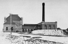
Calf Pasture Pumping Station
Zum Vergrößern Bild anklicken
| Name | Calf Pasture Pumping Station |
| Ortssitz | Boston (Mass.) |
| Straße | University Drive North |
| Art des Unternehmens | Abwasserpumpwerk |
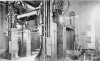
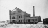
| Anmerkungen | Errichtet beim Bau Bostoner Entwässerungssystems in den den 1870er und 1880er Jahren. Südlich des alten Hafens, die später überwiend von der University of Massachusetts genutzt wird. Das Gebäude hat H-förmigen Grundriß: Kohlenlager für 2.500 tons Kohle (mit direkter Verbindung zum Hafen, im Gebäude steht der Schornstein), Kesselhaus im Verbindungsbau und Maschinenhaus mit zwei high-duty Leavitt-Pumpen und zwei Worthington-Pumpen für "storm duty". |
| Quellenangaben | [Clarke: Main drainage works of the city of Boston (1888) 59] http://blogs.umb.edu/pumpingstation/2013/04/ |
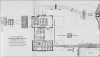
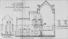
| Hinweise | [Clarke: Main drainage works of the city of Boston (1888) Pl. X]: Grundriß; [XI]: Querschnitt; [XII]: Rechenhaus; [XVI]: Außenansicht |
| Zeit |
Ereignis |
| vor 1700 |
Das erste Abwassersystem ist in Betrieb |
| 1823 |
Boston erhält den Charakter einer Stadt, und die Stadverwaltung übernimmt die Kontrolle über alle vorhandenen Entwässerungsanlagen |
| 1834 |
Zur Spülung der Abwasserleitungen wird erlaubt, daß die Dachentwässerung kostenfrei in die Leitungen eingeleitet werden darf |
| 1834 |
Der City Marshal übernimmt die Kontrolle der Abwasserleitungen |
| bis 1837 |
Von 1823 bis 1837 hat die Stadt 121.109,52 zum Bau von Abwasserleitungen aufgewendet, von dieser Summe wurden jedoch nur 26.431,31 eingenommen |
| 1838 |
Die Stadt entscheidet, ein Viertel der Gesamtkosten für die Kanalisation zu erheben |
| 1840 |
In Übereinstimmung mit einer Entscheidung des Obersten Gerichtshofs wird angeordnet, daß drei Viertel der Kosten für die Kanalisation durch die Anlieger bezahlt werden sollen, bezogen nur auf den Wert des Grundstücks und nicht der Gebäude |
| 1857 |
Es sind in Boston 6.500 Spültoiletten in Betrieb |
| 1869 |
In Boston gibt es ca. 100 miles = 160 km Abwasserleitungen |
| 1873 |
In Boston gibt es ca. 125 miles = 200 km Abwasserleitungen |
| 01.03.1875 |
Der Stadtrat autorisiert den Bürgermeister, eine Kommission, bestehend aus zwei Bauingenieuren und einer im Sanitärbereich erfahrenen Person, zu ernennen, die über den gegenwärtigen Zustand des Entwässerungssystems berichten und einen Plan für die Zukunft erstellen sollen. - Mitglieder der Kommission werden die Ingenieure E. S. Chesbrough und Moses Lane sowie der Arzt Charles F. Folsom |
| Dez. 1875 |
Der Bericht der Kommission, bestehend aus E. S. Chesbrough, Moses Lane und Charles F. Folsom wird vorgelegt. Er fordert, daß die Entwässerung bereits an den Häusern beginnen soll und daß die Leitungen belüftet werden sollen |
| 11.04.1876 |
Verabschiedung eines Gesetzes, welches die Stadt ermächtigt, eine Hauptentwässerungsleitung bei Moon Island in den Hafen zu verlegen |
| 17.07.1876 |
Es wird eine Summe von $40.000 für Untersuchungen zum Bau einer Entwässerungsleitung von der Tremont Street nach Moon Island und in das tiefe Wasser östlich von Castle Island bewilligt |
| 1877 |
Der Stadtingenieur berichtet über die Ergebnisse der vorbereitenden Untersuchungen |
| 09.08.1877 |
Der Stadtrat macht sich die Ergebnisse der Voruntersuchungen zueigen |
| 1885 |
In Boston gibt es ca. 226 miles = 362 km Abwasserleitungen |
| 1885 |
Es sind in Boston über 100.000 Spültoiletten in Betrieb |
| Produkt |
ab |
Bem. |
bis |
Bem. |
Kommentar |
| Abwasserförderung |
1885 |
Beginn |
|
|
|
| Zeit |
Objekt |
Anz. |
Betriebsteil |
Hersteller |
Kennwert |
Wert |
[...] |
Beschreibung |
Verwendung |
| 1885 |
Dampfkessel |
4 |
|
Kendall & Roberts, Charles River Iron Works |
Leistung je |
|
PS |
Feuerbüchskessel aus Stahl mit einer Dehnfestigkeit von 41,8 kp/qmm, Mantelstärke: 7/16" = 11,1 mm, Rohrwände: 1/2" = 12,7 mm, L= 39' 10" = 12.150 mm, 132 Röhren (D= 3" = 76,2 mm innen, L= 15' = 4575 mm); je zwei Feuerbüchsen L x B x H = 11' x 3,5' x 5' = 3355 x 1067 x 1524 mm, mit Verbrennungskammern |
|
| 1885 |
Schornstein |
1 |
|
unbekannt |
Höhe |
|
m |
gemauert, kreisrunder Querschnitt, D= 66" = 1,676 m (innen), H= 140' |
|
| ZEIT | 1885 |
| THEMA | Beschreibung |
| TEXT | As before stated, and as shown by the plan, the Main Drainage Pumping-Station is situated at Old Harbor Point, on the sea-coast in Dorchester, about a mile from any dwelling. In flowing by gravitation to this point the sewage has descended, so that it is from 11 to 14 feet below the elevation of low tide. To reach its final destination it must flow about 2 1/2 miles further, to Moon Island, and be high enough, after arriving at the storage reservoir on the island, to be let out into the harbor at the time of high water. That it may do this it must first be raised by an average lift of 35 feet. The essential parts of the pumping-station are: a filthhoist (so called), where the sewage passes through screens to remove solid matters which might clog the pumps; pump-wells, into one or more of which the sewage can be turned; pumping-engines to raise the sewage ; an engine-house to protect the engines; a boiler-house, containing boilers to furnish steam-power; a coal-house to store a supply of coal; and a dock and wharf, where vessels bringing coal can be unloaded. The filth-hoist is a solid masonry structure, extending from the surface of the ground down to below the main sewer. Its inside dimensions are 25 x 32 feet, and its exterior walls are from 4 to 5 feet thick, founded upon two courses of 10-inch timber. In excavating for building the filth-hoist, the ground, which consisted of wet sand, was held by round wooden curbs. The total depth of excavation was 35 feet, and the upper 12 feet were dug without bracing to natural slopes. Below this three tiers of 4-inch sheet planks, each 10 feet long, were driven, and were braced by circular ribs. The three curbs were 71.61 and 57 feet in diameter, respectively, and by this method of bracing an unobstructed space was secured for building the masonry. As will be seen by referring to Plates X. and XI., the main sewer passes through the westerly foundation wall of the filth-hoist. At this point the sewer has granite voussoirs cut to form a bell-shaped opening. Facing the sewer opening are two gate openings, protected by iron penstock gates, 7 x 6.5 feet each, through one or both of which the sewage flows. These gates are counterbalanced and are moved by hydraulic pressure derived from a city water-pipe. The pressure is sufficient to move them freely; but to start them when down, with a head of water against them, a hydraulic force-pump is added, by means of which the initial pressure can be increased to any extent required. Beyond the gates the structure is divided longitudinally by a brick partition wall into two parts, in each of which are chambers containing two independent cages, or screens, one before the other. The cages are rectangular in shape, 7 feet 8 inches high, 7 feet 3 1/3 inches wide, and 3 feet 4 1/4 inches deep. Their backs, sides, and tops are formed of 3/4-inch round iron rods, with 1-inch spaces between them. The cages are counterbalanced, and are raised and lowered by four small steam-engines. The steam for these engines, as well as for heating purposes, is brought underground from the boiler-house. The superstructure of the filth-hoist is 30 x 37 feet outside dimensions, and is built of quarry-faced granite dimension-stones, lined inside with brick. After passing through the cages the sewage is conveyed by one or both of two sewers, nine feet in diameter each, to galleries on either side of the engine-house substructure, from which galleries it can be admitted through gate openings to one or
more pump-wells, situated between the galleries. The bottom of the pump-wells is 19.5 feet below low-tide level and 36.5 feet below the surface of the ground. From the wells the sewage is raised by the pumps to its required elevation. The complete design of the pumping-station consists of an engine-house, two boiler-houses, and a coal-house, so arranged as to include a court-yard. The buildings are to be of dimensions suitable for containing eight pumping-engines with their boilers and other appurtenances. Only the portions of these buildings shown on the plan by full lines are at present constructed or needed. The foundation walls of the enoine-house ago-regate about 350 feet in length. They are 37.5 feet in height and nine feet thick at the bottom, where they rest on a timber platform, 24 inches thick, which also extends under the whole building, and furnishes a foundation course for the piers which support the
engines. To build the exterior walls trenches 16 feet wide were lirst excavated. A core of earth was left inside these
trenches until the walls had been erected, when it was removed to make place for the pump-wells and engine foundations. The exterior retaining and foundation walls were built of granite, and, although called rubble masonry, yet, owing to the sizes and shapes of stones used and the care taken in selecting and laying them, the work more nearly resembles a fair quality of roughly coursed block-stone work. The pump-wells and engine foundations are built chiefly of
brick, but contain in addition about 300 dressed granite stones. These stones are used for copings, as bearings for holding-down bolts, for lining gate and other openings, etc., etc. There are nine iron gates, with suitable attachments and shafting, operated by two small steam-engines. Eight of these gates, 4 feet 9 1/2-inches by 6 feet 3 1/2-inches each, control the flow of sewage from the side galleries into the four pump-wells. Another gate, 4 x 4 feet square, controls the admission of salt water from the salt-water conduit. This last-mentioned structure is a solid masonry conduit, with its bottom six feet below the elevation of low tide, and connects tide-water at the dock with one of the engine-house galleries. Its office is to conduct salt water to the engine-house for use in the condensers, and also to furnish an additional supply of water to the pumps for flushing or other purposes, whenever the amount of sewage received from the main sewer is insufficient for such purposes. As has been stated, the sewage is elevated to heights (depending at any time upon the depth of sewage in the reservoir) which average about 35 feet. As the city sewers receive rain-water, and as it is desired to take as much of this as possible, especially from certain districts, it follows that during short periods of time, when it rains, very much greater pumping capacity is needed than is usually sufficient. There must, therefore, be a pump, or pumps, to run continuously, and others to run only when it rains or thaws. The chief item of expense in pumping is the cost of fuel. For the sake of economy the pumping-engines for continuous service must do their work with as little consumption of fuel as possible, and to accomplish this an expensive machine can be afforded. For the engines which run only occasionally cheaper machines are more economical, the saving in interest on the first cost more than compensating for the extra fuel consumed by them. The pumping plant of the Boston Main Drainage Works includes two expensive high-duty engines and two cheaper lower-duty engines. The high-duty engines were designed by Mr. E. D. Leavitt, Jr., on general specifications prepared by the City Engineer,
Mr, Davis. They were built by the Quintard Iron Works, of New York, and cost about 115.000 each. As will be seen, it is a compound beam and fly-wheel engine, working two single-acting plunger-pumps. The steam cylinders are vertical and inverted, their axes coinciding with those of the pumps below them, the pistons of the engines and plungers of the pumps being connected in the same line with the ends of the beam. In designing these engines particular attention was given to the following conditions:
First. The distribution of the weight of the engine so as not to produce concentrated pressure on any part of the foundations.
Second. Great strength in the details and combinations of the parts, to render the liability of breakage a minimum.
Third. A proportion of the wearing surfaces such as will allow of an uninterrupted running for extended periods, with
the least wear.
Fourth. Easy accessibility of all the parts for examination, repairs, and renewals.
Fifth. An adaptation of the pumps and their valves to the peculiar duty required of them, i.e., to allow the passage of rags, sticks, and such other small bodies as will not be detained by the filth-hoist; and, in addition, a construction which will admit of the easy removal of an entire pump or any of its parts, without disturbing any important part of an engine.
Sixth, A high degree of economy in the consumption of coal.
Steam at a pressure of about 100 pounds is admitted from the supply-pipe A, through the side-pipe, B, to the steam-chests of the high-pressure cylinder, C. The distribution of steam is effected by gridiron slide-valves, having a short, horizontal movement imparted by revolving cams, D, fixed on a horizontal shaft, E, running along the bases of the cylinders, and driven by the crank-shaft through suitable gearing, F, The steam is cut off by the further revolution of the cam. The cut-off is adjustable, and controlled by the governor, G. After expanding to the end of the stroke the steam passes through the exhaust steam-chests to reheaters, H. These are cast-iron boxes, each containing about 750 5/8-inch brass tubes, two feet nine inches long. These tubes are filled with high-pressure steam, and in circulating about them the working steam is thoroughly dried. From the reheaters the steam is admitted to the low-pressure cylinder, I, where further expansion takes place. Thence it passes to the condenser, J, where it is condensed by salt water from a rose jet. K is the air-pump, and L the outboard delivery-pipe. The pumps, M, are hung to heavy girders supporting the engines by cast-iron hangers, N. A part or the whole of the weight of the pumps can also be supported by the wheels, O, resting on very strong cast-iron beams, P, built into the masonry on either side of the pump- wells. By disconnecting their hangers, the pumps, supported entirely by these wheels, can be run back on the beams (which then serve as tracks), and can be hoisted out of the pump-wells without interfering with the fixed parts of the engine. At Q are side galleries, through either of which the sewage reaches the gateways, E, leading into the pump-wells. In front of these gateways are iron gates, not shown on the plate, which admit or exclude the sewage. SS are the plungers. UU are man-holes. T is the force-main. The discharge from one pump passes through the delivery-chamber of the other. The plunger is represented as just completing its down stroke. The suction-valves (of
which there are 36 to each pump) are closed, and the delivery-valves (27 in number) are wide open, to permit the discharge of the sewage displaced by the plunger. In the other pump, at the same moment, the plunger would be completing its upward stroke, and the action of the valves would be reversed. The valves are of somewhat novel construction, and are shown by a section of a portion of one of the valve-plates, and the whole of one valve. As will be seen, they are simply rubber flaps, 3/4-inch thick, with wrought-iron backs and washer plates, the rubber faces bearing on cast-iron seats inclined at an angle of 45°. The valves form their own hinges, and open against guards or stops faced with leather. The clear opening is 4 1/2- x 13 1/2 inches. Pieces of board 10 inches wide and 24 inches long have passed through these valves. The ordinary working duty of these engines is nearly or quite 100.000.000 foot-pounds to each 100 pounds of coal.
The two pumping-engines for storm service were built at the Hydraulic Works, Brooklyn, L.I., by the firm of Henry R.
Worthington, of New York, from their own designs, and cost 45.000 each. They are of the Worthington duplex, compound, condensing type. Each machine consists in reality of two distinct compound engines coupled together, each engine working a double-acting plunger-pump. The capacity of each double engine is 25.000.000 gallons of sewage a day raised against a total head of 43 feet. This requires about twelve double strokes a minute and a piston speed of about 115 feet per minute. Steam at from 40 to 50 pounds is carried full pressure through the stroke of each high-pressure cylinder. Thence it passes through reheaters to the adjoining low-pressure or expansion cylinders, and is expanded during the reverse stroke. It is then admitted to the condenser and condensed by a jet of salt water. The steam cylinders are 21 and 36 inches in diameter respectively. They are steam-jacketed all over and suitably coated and lagged. The stroke is four feet. The steam-valves are moved by a novel and ingenious contrivance, called by the makers "the hydraulic link". Each engine has two small vertical cylinders, in which are plungers worked from the air-pump bell-crank. These plungers force water forward and backward through pipes leading to a cylinder in front of the high-pressure steimi-chest. In this cylinder is a piston connected with the main valve-stem of the engine, and the pressure imparted by the water alternately to opposite sides of the piston moves the valve-stem and effects the steam distribution. There are two pumps to each machine. Each pump is double-acting, being divided transversely in the middle by a ring which packs the plunger. The plunger is hollow, 45 inches in diameter, and has a 4-foot stroke. It displaces its bulk of sewage at each stroke in either direction. The positions of the valves, suction, and delivery chambers are indicated by the section. The valves are similar to those of the Leavitt engines. The engines and pumps are compact, and very conveniently arranged for inspection of all their parts. The guaranteed duty of these engines is 60.000.000 pounds of sewage raised 1 foot high by the consumption of 100 pounds of coal. To supply steam for the four engines there are four boilers, of a nominal capacity of 250 horse-power each. They were built by Kendall & Roberts, of Cambridge, Mass., and cost about 9.500 each. The boilers are of the horizontal fire-box, tubular form, and are made of homogeneous steel having a tensile strength of not less than 60.000 pounds per square inch, an elastic limit of 37.000 pounds, and an elongation of 30 per cent. The shell is 7/16 inch, and the tube-sheets are 1/2 inch thick. The length over all is 39 feet 10 inches. There are 132 tubes, 3-inch internal diameter, 15 feet long. Each boiler has two fire-boxes, 3 1/2 feet wide, 5 feet high, and 11 feet long. At the ends of the fire-boxes is a combustion chamber four feet long. The smoke-flues return into chambers containing flue-heaters, composed of 80 seamless brass tubes, 2| inches in diameter and 15 feet long. The heaters are on a level with the boiler-house floor, and can be run out from their chambers for cleaning or repairs. From the heaters the smoke passes by brick flues under the floor to the chimney. The chimney has a circular flue, 6Q inches internal diameter and 140 feet high. Among the minor engines and pumps appertaining to the pumping-station are four engines for raising and lowering the filth-cages; two engines for moving the gates in the engine-house galleries; two pair of double-acting steam-pumps for feeding the boilers; two double-acting steam-pumps for supplying salt water to the condensers; one large steam-pump for emptying the pump-wells and galleries in the engine-house. The buildings are warmed by a system of steam-pipes and radiators, and are lighted by gas made on the premises from gasoline. The coal-house is 129 x 59.5 feet in internal dimensions. It contains six coal-bins, or pockets, with a combined capacity of about 2,500 tons of coal. These bins are 23 feet high, and are built with solid walls formed of 2 x 6 inch spruce lumber, planed to an even thickness, and spiked flatwise on each other,
- a method of construction similar to that used in building grain elevators. The coal-house floor is made of Portland cement concrete. Iron cars are used for bringing coal from the bins to the boilers, and suitable tracks, turntables, and scales are provided. To furnish access to the pumping-station for colliers and other vessels, a channel one-half of a mile long was dredged out to the ship-channel in Dorchester Bay; 380 feet of dock-wall and a wharf 280 feet long were constructed. To facilitate the unloading of coal a coal-run, supported on a trestle 27 feet high, connects the wharf with the coal-house, and extends over the tops of the bins within the house. Above their foundations all buildings at the pumping-station were designed and built by the City Architect's Department. This building cost about 300.000. |
| QUELLE | [Clarke: Main drainage works of the city of Boston (1888) 59] |
|