|
|
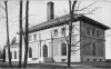
Spot Pond Pumping Station
Zum Vergrößern Bild anklicken
| Name | Spot Pond Pumping Station |
| Ortssitz | Malden (Massachusetts) |
| Ortsteil | Spot Pond |
| Art des Unternehmens | Wasserpumpwerk |
| Anmerkungen | Urspr. zur Versorgung der Städte Malden, Medford und Melrose aus dem Spot Pond, seit 1898 auch für Boston. |
| Quellenangaben | [Simoox: Middlesex Fells (2015) 39] [Brackett: Metropolitan Water Works (1905) 34] |
| Hinweise | [Brackett: Metropolitan Water Works (1905) 41]: Gebäude des Pumpwerks |
| Zeit |
Ereignis |
| 1867 |
Geschäftsleute aus Medford, Malden und Melrose gründen die "Spot Pond Water Company" für die öffentliche Wasserversorung und bauen ein Pumpwerk |
| 1898 |
Die Kontrolle über das Spot Pond -Pumpwerk geht auf das "Metropolitan Water Board" von Boston über. |
| 1900 |
Bau eines größeren Pumpwerks für das "Metropolitan Water Board" durch due Hochbaufirma "Shepley, Rutan & Collidge" (auch Erbauer der Chestnut Hill Pumping Station) im Neorenaissance-Stil für $120.000 |
| Produkt |
ab |
Bem. |
bis |
Bem. |
Kommentar |
| Trinkwasser |
1867 |
Gründung |
|
|
|
Zeit = 1: Zeitpunkt unbekannt
| ZEIT | um 1905 |
| THEMA | Pumpstation |
| TEXT | The Spot Pond pumping station building has exterior walls of gray Roman brick, with trimmings of buff Indiana limestone above a heavy base of pink Milford granite. The roof is covered with red Spanish tiles. The building contains an engine room 105 feet by 60 feet, a dynamo room 49 feet by 16 feet, a boiler room 53 feet by 49 feet, and a coal house 71 feet 8 inches by 40 feet, having a storage capacity of 1,000 tons. The chimney is 125 feet high, 11 feet square at the base, 9 feet at the top, with a flue 4 feet in diameter. The engine room contains at present two engines, one of 10,000,000 gallons daily capacity, designed by E. D. Leavitt for the City of Boston, and erected by the Blake Manufacturing Company in 1895 at the Mystic pumping station, whence it was removed in 1899. and one of 20,000,000 gallons daily capacity erected by the Holly Manufacturing Company of Lockport, N. Y. The engine room contains space for a third engine. The Leavitt engine has steam cylinders 21 inches and 42 inches in diameter, operating two differential plunger pumps. The plungers have diameters of 14 7/8 and 21 inches, and both pump plungers and steam pistons have a stroke of 48 inches. The Holly Manufacturing Company's engine has steam cylinders 22 inches, 41^ inches and 62 inches in diameter, pump plungers inches in diameter, and both pistons and plungers have a stroke of 60 inches. The boiler room contains three vertical internally fired fire tube boilers 92 inches in diameter, 29 feet 4 1/2 inches long, containing 256 2 1/4 -inch tubes 15 feet long. The boiler feed water is heated by passing through a Green economizer containing 144 tubes. By these pumps water is raised from Spot Pond 108 feet to the Fells Reservoir, and 137 feet to the Bear Hill Reservoir, and from these reservoirs distributed to the elevated portions of the northern part of the Metropolitan District. |
| QUELLE | [Brackett: Metropolitan Water Works (1905) 39] |
| |
| ZEIT | um 1905 |
| THEMA | Spot Pond Reservoir |
| TEXT | Spot Pond, the largest distributing reservoir, has an area of 308.7 acres and is situated in the northern part of the
Metropolitan District in the town of Stoneham, about eight miles from the State House and eleven miles from the Chestnut Hill Reservoir. It has been formed by raising and improving a large natural pond which, previous to the construction of the Metropolitan Works, was used as a source of supply for the cities of Maiden, Medford and the town of Melrose. The improvement of the pond was made by lowering its surface 12 feet, thus exposing the greater part of the bottom, and then excavating the mud so as to give a clean gravel or sand bottom over the greater part of the exposed area. In places where the mud was so deep that it could not be removed without going below the level of the water in the pond, the mud was covered with clean gravel or sand 12 inches in thickness. The earth was also excavated from the shallow portions of the pond so as to give everywhere a depth of 15 feet of water when the pond is full. The pond was raised 9 feet above its old level, necessitating the building of six dams with concrete corewalls from 165 to 621 feet long, and from 10 to 28 feet in height, and four earth dikes; also the construction of a system of drainage to care for water which, by the construction of the dams, is prevented from entering the pond. This drainage system consists of 2,200 feet of open channel, 1,600 feet of 24-inch vitrified pipe, 1,050 feet of concrete masonry conduit 4 feet wide,
3 1/2 feet high, and 2,400 feet of 30-inch cast-iron pipe. The drains collect the water from 766 acres which formerly
drained into the pond, and discharge it into the brook which was the outlet of the pond previous to its improvement. Water enters and leaves the pond at two points located about 3,000 feet apart. At each of these points there is a concrete masonry chamber located at the shore, in which there are sluice gates for controlling the flow of water. From each chamber two inlets into the pond are provided so as to draw water from different depths. From the east chamber there is a concrete masonry conduit 5 feet high, 4.5 feet wide, extending 565 feet into the pond, with its invert 25.2 feet below high water. The high level inlet consists of a 48-inch pipe 58 feet in length. From the south gate-chamber a concrete masonry structure containing two conduits placed one above the other, extends 200 feet into the pond. The invert of the lower conduit is 26 feet below high water, and the opening into the upper conduit is in the top of the masonry structure 12 feet below high water. From the gate-chambers cast-iron pipes convey the water into the Metropolitan District. |
| QUELLE | [Brackett: Metropolitan Water Works (1905) 43] |
|