|
|
Northwestern Elevated Railroad
Zum Vergrößern Bild anklicken
| Name | Northwestern Elevated Railroad |
| Ortssitz | Chicago (Ill.) |
| Straße | Fullerton Avenue |
| Art des Unternehmens | Hochbahn |
| Anmerkungen | Mit Kraftwerk an der Fullerton Avenue, nahe der Southport Avenue. |
| Quellenangaben | [Street railway review 10 (1900) 369] |
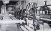
| Hinweise | [Street railway review 10 (1900) 369]: Außenansicht, Schalttafel, Grundriß und Querschnitt |
| Produkt |
ab |
Bem. |
bis |
Bem. |
Kommentar |
| Hochbahnverkehr |
|
|
|
|
|
| Bezeichnung |
Bauzeit |
Hersteller |
| Dampfmaschine |
um 1900 |
Edw. P. Allis & Co., Reliance Works |
| Dampfmaschinen |
um 1900 |
Edw. P. Allis & Co., Reliance Works |
| Zeit |
Objekt |
Anz. |
Betriebsteil |
Hersteller |
Kennwert |
Wert |
[...] |
Beschreibung |
Verwendung |
| 1900 |
Dampfkessel |
12 |
|
Babcock & Wilcox Co. |
|
|
|
Wasserrohrkessel |
|
| 1900 |
Dampfpumpen |
3 |
Kesselhaus |
Worthington Pump and Machinery Corporation |
|
|
|
senkrechte Duplexpumpen, für Kesselspeisung |
|
| ZEIT | 1900 |
| THEMA | Kraftwerk |
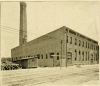
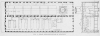
| TEXT | The power plant of the Northwestern Elevated Railroad Co., of Chicago, now approaching completion, is the sixth of the great stations for generating electric power which have been built by the Yerkes interests in developing the urban transportation systems of the north and west divisions of the city, and is no exception to the others in embodying the latest and best practice in all that is conducive to economical operation. The original plans for the mechanical features of this station were drawn by the late Mr. Salvator Potis, jr., who also designed the older Yerkes plants; the electrical equipment of the station was desigecd by Mr. J. K. Chapman, electrical engineer for the Yerkes elevated roads and for the "Chicago Union Traction Co.", and he has made some changes in the plans as first adopted. The engineer in charge of the work was Mr. Z. E. Knapp. The building is on Fullerton Ave., near Southport Ave., about 1.000 feet west of the elevated structure and about midway between the two extremeties of the line. It is of yellow brick with concrete roof and checkered steel floor. The outside dimensions of the building are 254 feet 10 inches by 112 feet; a longitudinal wall separates the boiler and engine rooms. The basement floor is 9 feet 4 inches below and the coping of the side walls 49 feet 6 inches above the street level. The basement is 12 feet 4 inches high, and extends under the entire building: it is finished in granitoid with a concrete floor. At the south end of the building the basement
extends out to the curb line. The boiler room is 50 feet 2 inches wide inside: it contains 12 Babcock & Wilcox water-tube boilers set in batteries of two, with extended-front Murphy automatic smokeless furnaces. From the furnace front to the west wall is 13 feet, and behind the boilers is a passageway 4 feet 7 inches wide. The floors of the engine and boiler rooms and at the same level, and the height from the floor to the bottom of the root trusses, 38 feet 4,5 inches, is the same in both rooms, The basement under the boiler room contains the smoke flues and the blow-off piping, and the ash conveying machinery will also be placed there. The three boiler feed water pumps, which arc of the vertical duplex admiralty type made by the "Henry H. Worthington Co.", are in the basement just west of the stack.
South of the stack in the boiler room are two 2.000-horsepower Berryman feed water heaters; the condenser is between the stack and the partition wall of the building. The exhaust from the feed and air pumps is taken to these heaters, which may be connected in series or in multiple, one or both used, or both cut out. One of the most interesting features of the boiler installation is the steam header which is shown in plan in Fig. 9. This header consists of six lengths of 28-inch wrought iron lap welded pipe with the flanges welded on; it is divided into three sections each
about 50 feet long, and each of these sections is anchored near its middle point as indicated in the drawing. The space between two sections is about 14 feet and across this is the expansion connection made of four Us of 8-inch steel pipe.
The four U's enter a multiple cross-header at each end. and these cross-headers are each connected to the adjacent section of 28-inch pipe by a 16-inch Chapman gate valve. The branches to the engines are 8-inch for the small engine and 12-inch for the large ones. An auxiliary steam header 6 inches in diameter and tapping each section of the main header is provided for the auxiliary machinery. The feed water supply pipes are in duplicate and are carried on top of the boilers. The stems of those valves which are to be used habitually are connected through universal joints to long rods which extend down to the front of the furnaces where they are within reach of the boiler room attendants. The flue dampers being at the rear end of the boiler settings, Mr. Chapman designed an ingenious arrangement for manipulating
them from the furnace front. The damper shaft from each boiler projects through the wall of the setting, and is fitted with a quadrant of gear teeth; meshing with the teeth of the quadrant is a worm, the shaft of which extends through the extended combustion chamber and in front of the boilers terminates in a handwheel. The center line of the stack is 215 feet from the south wall of the building; when the extension ultimately contemplated is completed the building will be 430 feet long, with the stack in the center. The stack is 27 feet square at its base and rests on a foundation of
piling, driven 30 inches between centers, on top of which is a concrete footing 31 feet square and 5 feet thick.
At 35 feet above the ground the external outline of the stack becomes octagonal. The thickness of the walls is gradually reduced from 44 inches at the base to 13 inches at the top. The top has a cast iron hood; the internal diameter at the top is 16 feet and the short diameter of the external octagon 21 feet 3 inches. The total height of the slack above (he street level is 203 feel and from the bottom of the smoke flue is 217 feet 6 inches. For the first no feet there is an inner shaft of fire brick, 16 feet internal diameter, and decreasing in thickness from 17 inches at the base to 9 inches near the top. A curved partition wall divides the stack for the first 20 feet; the flue inlet is 16 feet high by 4 feet wide.
The building as it now is contains room for five units, one of 750 kW and four of 1.500 kW capacity. Only three of the large units are now installed. The engines were all built by the "E. P. Allis Co.", of Milwaukee, and are of the cross compound condensing Corliss type direct connected to Siemens & Halske generators. The engine room is 57 feet 7 inches wide by 250 feet long. The large engines have cylinders 30 and 60 inches by 60 inch stroke, and are designed to run at 75 r.p.m. The center lines of the high and low pressure engines are 24 feet 8 inches apart; the flywheel is 25 feet in diameter. Each engine has two governors; one regulates the working cut-off in both cylinders and the other trips a safety cut-off valve when a safe speed is exceeded. The smaller engine has cylinders 23 and 46-inches by 48-inch
stroke and runs at 80 r.p.m. The flywheel for this engine is 20 feet in diameter. The shafts for these engines were made by the "Bethlehem Steel Co." and are of fluid compressed open-hearth steel hollow-forged over a mandrel. For the large engines the shafts are 28 inches in diameter at the flywheel and 22 inches at the bearings; the axial hole is 8 inches in diameter. In Fig. 4 are shown two vertical sections of the separator for one of the large engines. The shell is of 1/2-inch steel, 42 inches inside diameter, and the heads are of 5-8-inch flange steel bent to a spherical surface of 42-inch radius. The length of the separator over the head is 9 feet 4,5 inches; it is supported on a cast iron base, which brings the top 9 feet 11 inches above the floor. The longitudinal seam of the shell is a double strap, double-riveted butt joint with 7/8-inch rivets 4 inches on centers; the transverse joints are single riveted. All rivet holes are drilled. The steam enters the separator at one side at a point 5,75 inches below the center and impinges on a shield in front of which are baffle plates arranged as shown in the drawing. The pocket at the lower part of the shield is provided with a pipe to carry the intercepted water below the perforated plate which prevents the current of steam from coming in direct contact with the water accumulated in the separator. This horizontal plate is of 1/4-inch steel in three pieces, and perforated with 129 holes 1 inch in diameter; it is 16 inches from the bottom of the separator. The exit to the engine is a 10-inch pipe located with its center 19 inches from the lop of the separator The receiver and separator lor each unit arc located in the basement between the foundations of the high and the low pressure engines, and this permits all of the piping, both steam and exhaust to be placed under the engine room floor and arranged compactly. Fig. 4 shows the piping for engine No. 2. It will be noted that the supply pipe, 12 inches in diameter, as brought from the boiler room is about 5 feet above the inlet to the separator, and in the vertical
section is a safety stop valve: this valve is of the sector type, similar to the Corliss engine valve, and is normally open with the operating lever weighted. It is held in this position by a pawl connected to a slow-running governor on the engine; when the engine speed rises above the maximum limit as set, the pawl releases and the suspended weight closes the valve by gravity. The receiver is 61 inches in diameter and 10 feet 6 inches high. The 14-inch exhaust from the high pressure cylinder and the 20-inch supply to the low pressure cylinder open into the receiver 2 feet 6 inches from the top. The exhaust pipe from the low pressure cylinder is 22 inches until it is clear of the engine foundation and a 22-inch Wainwright joint 2 feet 6 inches long; thence it is 28 inches in diameter to the exhaust main. The live steam lines are all extra heavy lap-welded wrought iron pipe and the exhaust piping of cast iron. The live steam valves are extra heavy-ribbed, bronze-seated gate valves of the Chapman make. The working pressure is 160 pounds. The city of Chicago has a 12-foot brick tunnel in Fullerton Ave., through which water is drawn from the lake to flush the north
branch of the Chicago River, and the company has arranged to take its supply of condensing water from this tunnel. The intake is a 30-inch pipe, which is carried along the east wall of the building, just below the level of the basement floor; the return to the tunnel is a 36-inch pipe along the longitudinal partition wall of the building, also below the basement floor. The original design of this station contemplated the use of a separate condenser for each engine, but this was changed and a central condenser of the Weiss counter-current type was installed. This condenser was built by the "Southwark Foundry & Machine Co." and is large enough to take care of the ultimate capacity of the plant, 14.000 h.p. It is very interesting to know that the installation of this central condenser instead of the independent condenser first contemplated made a saving of over $10.000 in the cost of the piping and enabled the building to be made about 30 feet shorter. The auxiliary machinery at present installed is for 7.000 h.p. of engines only. It consists of a steam engine driving the air pump tandem and belted to the circulating pump, the latter being in the basement. The air pump is an air compressor of improved type, with a Weiss positive slide valve, and works free from water, the
intake of the pump being from the top of the condenser. The circulating pump is of the Bibus rotary type and handles only the cold injection water. Fig. 5 shows the Weiss condenser in elevation. The exhaust main, which is in the basement of the engine room between the engine foundations and the dividing wall, increases in size from 22 inches for the small engine to 55 inches after passing the fourth one, and joins an immense elbow in which the openings are 65 inches in diameter. The vertical 65-inch pipe is carried up and opens into the enlarged head of the condenser 10 feet in diameter; from this head a pipe extends down to near the bottom of the hot well, and constitutes a water leg or barometric tube. The condensing water is handled by the Bibus pump and delivered to the condenser through a 22-inch pipe at a point about 6 feet above the steam inlet. From the lop of the condenser a pipe is taken and carried down to
the bottom of a smaller well, where it opens under water, forming a second barometric tube. Near the top of this smaller barometric tube is placed a separator, from which a 9-inch suction pipe leads to the air pump. A small pipe connecting the main condenser vessel with the small barometric tube insures, at all times, a sufficient quantity of water in the small auxiliary hot well to seal the tube. The water from the auxiliary hot well flows over a weir into a bucket (marked B in the drawing), the latter having a hole in the bottom which allows the normal flow to escape. But in the event of a sudden and heavy overload, when the supply of water has been adjusted for a light load, causing the temperature of the discharge to reach the boiling point, an abnormal quantity flows over and down the small barometric tube filling the bucket, thus by the increased weight opening a free air valve into the condenser. This reduces the vacuum to just below the boiling point and maintains it there until the attendant adjusts the quantity of injection to meet the increased demands, and all without a total loss of vacuum. Two 28-inch pipes, with a Blake back-pressure valve in each, connect the 65-inch exhaust riser to a 40-inch free exhaust pipe opening above the roof. The boiler feed is drawn from the condenser hot-well at practically the same temperature as the exhaust steam entering the condenser. The advantages claimed for the Weiss central condenser, aside from the simplification in the piping and economy of room already mentioned, are the less power required to drive the machinery, the less amount of cooling water (one-half to two-thirds) required as compared with the ordinary jet condenser, the lesser head on the circulating pump, and the higher temperature of the hot-well. Since the supply of injection water is constant and independent of the vacuum, a sudden increase of load or a leak does not act to reduce the vacuum when it is most needed, and thence the condenser
is very reliable in its action. The station has been in partial operation since June 1st and the performance of the condenser has been all that could be desired; the temperature of the exhaust has been between 115 and 118 degrees F.
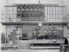
In addition to the live steam and exhaust piping and the engine separators and receivers, the engine room basement also contains the electric cables to and from the switchboard. These are placed overhead along the east wall of the building. Turner oil filters and pumps for forcing the oil to the engines are also in the engine room basement. For feeding cylinder oil an oil pump, made by the "Phoenix Metallic Packing Co.", is attached to each of the low pressure engine cylinders and is driven from the reciprocating parts of the engine; sight feed lubricators of the usual type are used on the high pressure engines. The switchboard is located along the east wall of the engine room opposite the stack. It is built in two decks, the station panels being placed below and the feeder panels above. The construction
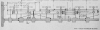
of the switchboard is apparent from Fig. 14. and Fig. 15 shows the arrangement of the panels, and Fig. 16 the details of a feeder panel. As arranged at present, current from three of the generators passes through the upper of the two Thomson wattmeters and that from the fourth unit through the lower one. On the feeder board an extra or emergency panel has been provided; it is the one immediately over the wattmeter panel of the lower board. An auxiliary bus bar (the upper one in Fig. 15) connects all the feeder panels, including the emergency one; the regular feeder panels have two
single throw switches, one for connecting to the station bus and one for connecting to the auxiliary bus, and the emergency panel but one switch. In event of an accident to the circuit breaker or other apparatus the panel affected is disconnected from the main bus, connected to the auxiliary, and the switch on the emergency panel thrown in. General Electric circuit breakers. Thompson wattmeters, and Weston ammeters and voltmeters are used. The company has contracted with the John A. Mead Manufacturing Co., of New York, (or the construction of a complete coal and ash conveying plant, which will not be completed for some months yet. Temporarily the coal is wheeled into the building on a wooden platform built in front of the furnace and level with the tops of the hoppers. The lot owned hy the company is 595 feet lo inches long, and the present building 254 feet 10 inches. The coal-storage building is 24 x 80 feet, by feet 6 inches high at the caves and 46 feet 7,5 inches at the ridge, and is at the extreme north edge of the lot. This storage building is to be connected with the boiler room by an overhead passage way for the conveyors and by a tunnel. The
overhead way is 38 feet 3,5 inches above the ground, and its internal dimensions are 6 feet 6 inches by 8 feet; the tunnel is 6 x 9 feet inside and the foundations are 14 feet 6 inches below grade. About so feet north of the power station are located the receiving hoppers into which the coal is unloaded directly from the freight cars. Just north of these are two ash tanks which can be discharged into cars or wagons. The coal crushing machinery is at the hoppers and from here conveyors take the coal to the elevator at north of the storage building, and thence to storage hoppers, or to the bunkers in the boiler room. Ashes are taken by a conveyor from the basement of the boiler room up and around and finally dumped in the steel ash tanks. The capacity of the conveying system is 50 tons per hour. The coal storage building holds 1.500 tons and the bunkers in the boiler room hold 300 tons. The chief engineer of the station is Mr. John Wright. |
| QUELLE | [Street railway review 10 (1900) 369] |
|