|
|
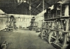
Wasserwerk Chicago, Fourteenth Street Pumping Station
Zum Vergrößern Bild anklicken
| Name | Wasserwerk Chicago, Fourteenth Street Pumping Station |
| Ortssitz | Chicago (Ill.) |
| Straße | Fourteenth Street |
| Art des Unternehmens | Wasserpumpwerk |
| Anmerkungen | Lage 14th Street und Indiana Avenue. Baubeginn 1888, Inbetriebnahmejahr 1891, volle Inbetriebnahme Dez. 1892. Hat seit 1913 auch eine turbinen-getriebene Zentrifugalpumpe für 25.000.000 gal/d. |
| Quellenangaben | [A century of progress in water works, Chicago (1933) 30+46] [Water works system of the city of Chicago (1917) 42] |
| Produkt |
ab |
Bem. |
bis |
Bem. |
Kommentar |
| Trinkwasserförderung |
1891 |
Beginn |
1933 |
[Century of progress] |
|
| ZEIT | 1893 |
| THEMA | Versuche an den Allis-Dreizylinder-Pumpmaschinen |
| TEXT | Chicago, III., July 5th, 1893.
Mr. Samuel G. Artingstall, City Engineer:
Sir The undersigned beg leave to submit their final Report of the Duty and Capacity Trial of the Pumping Engines at the Fourteenth Street Station. The purpose of the trial was to determine the duty and capacity of three pumping engines built by the Edward P. Allis Company of Milwaukee, Wis. The contract requires that the engines shall develop a duty of one hundred and twenty-five million (125,000,009) foot pounds for each one thousand (1,000) pounds of feed water evaporated, while pumping at the rate of fifteen million (15,000,000) United States gallons in twenty-four (24) hours for each engine, against a head of one hundred and twenty-five (125) feet, at a piston speed of one hundred and sixty-two (162) feet per minute, and with a steam pressure of one hundred and twenty (120) pounds per square inch. As originally drawn, the contract required the duty to be based on each one hundred (100) pounds of the best quality of Lehigh (Anthracite) coal burned; but the city, for its own benefit, had altered the grates and furnaces prior to the trial, adapting them to the use of inferior grades of coal, at the same time agreeing with the builders that the duty should be based upon the feed water as above stated.
DESCRIPTION OF THE ENGINES.
The engines are three in number, alike in all respects, and are designated No. 1, No. 2 and No. 3. In type they are triple-expansion, direct-acting, crank and fly-wheel, vertical engines with plunger pumps. Each engine has three steam cylinders in which the pistons are double acting, and three water plungers, which are single acting; all being on vertical axes. The steam cylinders are placed side by side on "A" frames vertically over the pumps and each piston is connected rigidly to its corresponding plunger. The reciprocating parts are of such weight as to equalize the work of the upward with that of the downward stroke, thus enabling the double-acting piston to drive the single-acting plunger without especial assistance from the fly-wheels. Between the steam cylinders and the pumps is the crankshaft, carrying two fly-wheels. The cranks are set 120° apart and each is connected by a rod of usual form to its corresponding crosshead, which works in guides in the cast-iron frame. Each piston is connected to its crosshead by two piston rods, while the connection of the cross-head to the plunger below is by four rods, which avoid the shaft. The pumps are placed in a dry well, so low that the water flows to them. The suction pipes branch from one suction main which connects with the tunnel well outside the building. The pumps discharge directly into the street mains without a stand pipe. The plungers are packed outside with hemp. All the steam and exhaust valves are of the Corliss type and are placed in the cylinder heads. The cut-off of the high pressure cylinder is controlled by a governor, while the cut-offs of the intermediate and of the lower pressure cylinders are adjustable by hand. The cylinders are all steam jacketed and the receivers have heaters. The jackets of the high pressure cylinder and the intermediate cylinder, and the heater of the first receiver are supplied with steam direct from the boilers ; while the heater of the second receiver and the jacket of the low pressure cylinder are supplied with steam at a reduced pressure—about 45 pounds by gauge. The condensation of the jackets and heaters is discharged through traps and led directly to the suction pipe of the feed pump. The feed pump, air pump and a small pump for supplying air to the air chambers, are all driven by an arm on the low pressure plunger.
DESCRIPTION OF THE BOILERS.
The boilers are of the horizontal tubular type, set in brickwork and fired below the shell. They are nine (9) in number. At the time of the trial six of them had been provided with "Hawley Down Draft" furnaces and the three others were in the process of being so altered. The gases pass downward through the fire on the upper grate, over the lower grate and bridgewall, thence along the shell to the back end, returning through the tubes, after which they pass back over the top of the shell to a horizontal iron flue which leads to the chimney. The principal dimensions of the boilers are as follows:
Number of boilers... 9
Diameter of shell in inches. 62
Length of shell in feet. 20
Number of tubes... 49
Diameter of tubes in inches. 4
Length of tubes in feet. 20
Shell and heads. 188
Water heating surface in square feet ] 9 |"
Total.1,228
Area of upper grate (Hawley Furnace), square feet. 22
Area of lower grate in square feet. 22
Area of chimney in square feet. 38.5
Height of chimney in feet. 125
CONDUCT OF THE TRIAL.
The three engines were subjected to trial simultaneously. They had been in continuous service for about five months, and the trial conditions differed from those of normal service only so far as the weighing of the feed water required. At times it was found necessary to throttle the discharge mains, in order to maintain the contract head. No means existed for ascertaining the slip of the pumps. Hence the volume of water pumped was measured by the displacement of the plungers, each of which was carefully measured. In the results given no allowance has been made for slip. The pressure in the discharge pipe was measured by a gauge at each engine, the connection being throttled so as to leave a slight vibration to the pointer. These gauges were tested both before and after the trial. The level of the water in the well was measured by a copper float and rod, the latter being graduated in pounds and tenths so as to give directly the pressure due the elevation of the discharge gauge above the water in the well. This reading was verified. During the trial no leakage occurred at the plungers. The feed water was measured by weighing. Two platform scales were placed on an elevated platform, each carrying an iron tank of one thousand pounds capacity. Below them was a third tank from which an independent feed pump drew the water. Each scale was accurately balanced with its empty tank before the trial. In operation these tanks were filled alternately until the beam tipped at 1,000 pounds, and were discharged as required into the lower tank. The scales were tested especially for the trial by the City Sealer of Weights and Measures and found correct. Each entry in the feed water log represents therefore one thousand pounds. The feed water was obtained from the feed pumps on the main engines and led by a pipe to the weighing tanks. Here the valves were handled by an employe of the station in the presence of the observer. This observer had no other duty than to record the feed water. The temperature of the feed water was taken at the tanks and also as it entered the boilers. The thermometer in the feed pipe at boiler No. 7 became deranged shortly before the trial began and its reading has been neglected. In calculating the heat units in the steam the temperature of the feed water at the weighing tanks has been employed. Since the feed water passed through almost identically the same pipes as it does in normal service, no occasion exists for estimating frictional or other resistances excepting the theoretical work of injecting the feed water into the boiler. This work is deducted from the gross work of the pumps. The independent feed pump employed during the trial obtained steam from boiler No. 8, in which the pressure was kept about forty pounds lower than in the other boilers. The coal burned was Hocking Valley bituminous coal. It was weighed in cars; the net weight being nominally 2,000 pounds in each car. A slight correction was found necessary in the tare and was applied. The quality of the steam was measured at intervals of three hours by a throttling calorimeter of Prof. R. C. Carpenter's latest design. The instrument was located near the throttle valve of Engines No. 1 and No. 2. Engine No. 3 was assumed to have the same quality of steam as engine No. 1, since both took steam from the same pipe. A single trial in the vertical steam pipe over boiler No. 7 indicated one-quater of one per cent, less moisture in steam than at engine No. 2. The steam gauges on the boilers and also those on the engines were tested before the trial. All gauges, counters and thermometers were read every fifteen minutes. The duration of the trial was forty-eight (48) hours, the observers being divided into two watches of twelve hours each. In addition to the trial observers, the Edward P. Allis Company had a number of observers sufficient to keep a complete set of independent logs. On account of the multiplicity of cylinders and the length of the trial, it was deemed advisable to take no indicator diagrams during the Duty Trial. The trial commenced at 12, noon, May 19. The condition of the fires was observed ; the gauges were read; the height of water in each boiler was determined by a string on the glass gauge, and the height of water in the lower tank noted. In the engine-room all the counters were read simultaneously. The trial was closed in the same way at 12, noon, May 21. During the trial four boilers were used. A higher evaporative efficiency could doubtless be obtained by using five or six boilers with the same total grate area. |
| QUELLE | [E. Allis & Co.: Official test of three triple expansion pumping engines at 14th Street Pumping Station (1891)] |
|